A350 Hydraulic System: A Detailed Schematic Overview
A350 Hydraulic System: A Detailed Schematic Overview
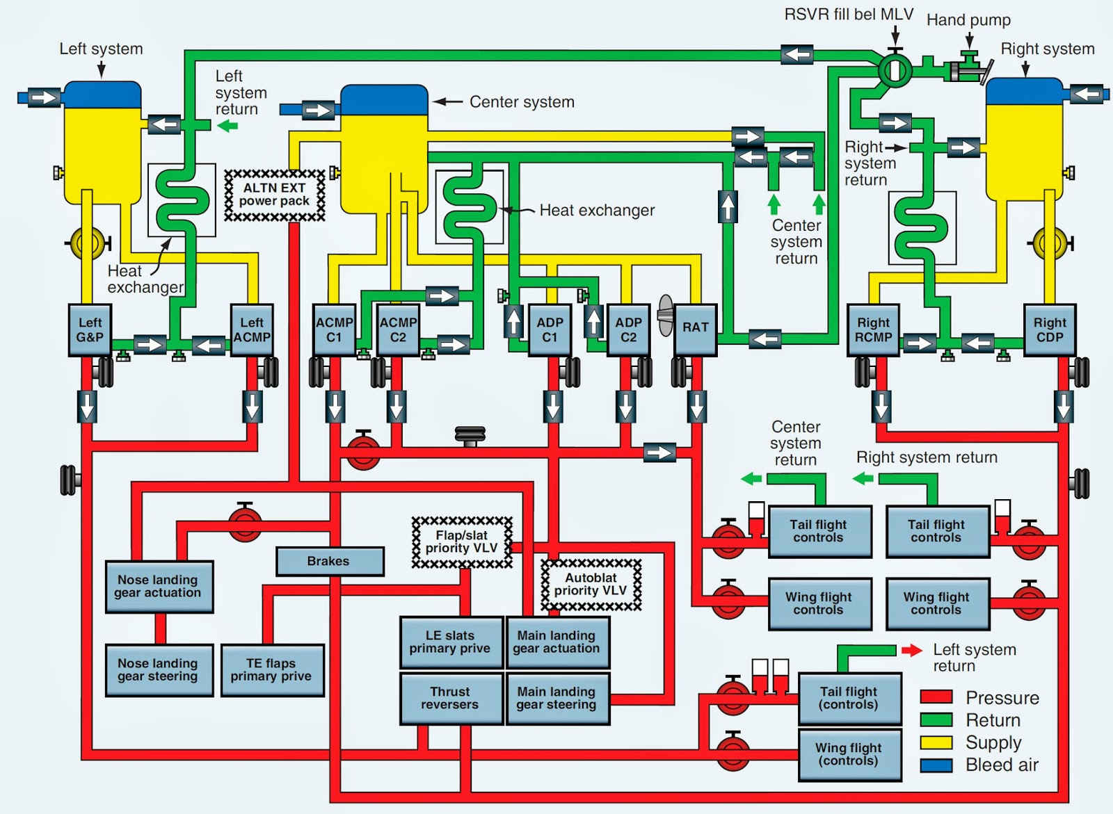
The Airbus A350’s hydraulic backbone powers almost every flight-critical operation, from high-lift amplifier deployment to actuator control during takeoff, climb, and landing. At its core lies a sophisticated, carefully engineered hydraulic system designed for reliability, redundancy, and precision in the harshest aviation environment. At the heart of this system is a dual-redundant multi-phase hydraulic network—engineered to maintain performance even under extreme conditions.
This article delivers a comprehensive schematic exploration, revealing the precision and integration behind the A350’s hydraulic architecture. A350 Hydraulic System operates on a dual-source principle: two independent circuits—Hydraulic System 1 (HS1) and Hydraulic System 2 (HS2)—each feeding critical flight control surfaces and gear mechanisms. Each system consists of high-pressure pumps, accumulators, accumulators, and power relief valves, operating typically between 3,000 and 5,000 psi.
As Airbus engineering chief Marco Dallaporto explains, “The redundancy isn’t just a backup—it’s engineered into the flight envelope. Should one system fail, the other instantaneously assumes control, preserving safety and operational continuity.” This architecture directly supports the A350’s classes of use, enabling high-intensity missions without compromising reliability.
Central to the A350’s hydraulics is a closed-loop power composition system, integrating high-strength composite oil resistant to extreme temperatures and degradation.
The fluid flows through precision-machined **hydraulic lines**—strategically routed along load paths to minimize pressure drop and mechanical wear. These lines, typically made from reinforced aluminum alloy or Aramid fiber composites, are fused at critical junctions using flask welding or brazing techniques, ensuring leak-free integrity while withstanding cyclic stress.
Redundancy and System Segmentation: Designing for Fail-Safe Operations
Integral to the A350 hydraulic system is its segmentation by failure modes and flight phases.The architecture divides the system into hydraulic bays dedicated to specific functions—landing gear extension, flaps, spawn panels, elevators, rudders—each supported by dedicated pump assemblies and control valves. This segmentation ensures that a fault in one circuit does not cascade across the entire system, a vital attribute confirmed by Airbus’ rigorous testing protocols. An impactful example is the independent actuation of spar and trim spools in the landing gear.
During extension, HS1 supplies primary pressure, while HS2 maintains a safety cushion in case of pump failure. The **dual master cylinders** at each primary flight control (elevators, rudders, ailerons) receive hydraulic pressure through distinct pathways, with decision valves automating transfer between systems to prevent single-point failure. According to Airbus’ Mechanical Systems Technical Bulletins, “Every valve, every hose, every reservoir is engineered not just for performance, but for fault tolerance—designed to fail gracefully, never catastrophically.”
Key Components: Hydraulic Pumps, Reservoirs, and Accumulators
At the core of hydraulic power generation are the **auxiliary and main hydraulic pumps** located in the engine-powered hydraulic generator (EPHG) and auxiliary power unit (APU).While the high-bypass engines drive EPHG units primarily during cruise, auxiliary pumps maintain system pressure during taxi and ground operations—critical for start-up sequences and emergency scenarios. The A350 typically carries two main accumulators per system: nitrogen-charged accumulators store energy to bridge pump outages during transient loads, ensuring uninterrupted actuation during high-speed extension or sudden load changes.
- Hydraulic Master Cylinders: Installed at each flight control surface, these cylinders convert hydraulic pressure into mechanical force, actuating surfaces with high responsiveness and repeatability.
Each is isolated for redundancy—failure of one does not disable actuation of conflicting systems.
- Accumulators and Fluid-management Valves: These components buffer pressure spikes, absorb shock loads during abrupt maneuvers, and maintain steady pressure when pump flow is interrupted. Their strategic placement near landing and flight control units optimizes response time.
- Control and Safety Valves: Fleet-grade pressure control systems include flow restrictors, directional control valves, and emergency relief valves calibrated to interrupt flows above 6,500 psi to prevent component rupture. These valves are spare-capable and undergo automated diagnostics pre-flight.
Advanced Monitoring and Diagnostics
Modern hydraulics demand real-time health monitoring—and the A350 delivers with an integrated **Condition-Based Monitoring System (CBMS)** embedded within the hydraulic architecture.Sensors embedded along main lines and at each actuator monitor pressure, temperature, flow rate, and fluid contamination levels. Data streams feed into the aircraft’s Integrated Modular Avionics (IMA) network, enabling predictive maintenance and early fault detection. As Airbus Flight Systems Engineer Luca Moretti notes, “The system doesn’t just react—it foresees.
Machine learning algorithms flag anomalies like micro-leaks or valve degradation before they reach critical thresholds.” These diagnostics interface with the Flight Management System (FMS) and Engine Health Monitoring (EHM), providing pilots and engineers actionable alerts. Redundant sensor arrays ensure that no single data loss compromises system awareness—mission-critical in long-haul operations where maintenance access is limited.
Operational Impact and Pilot Experience
For pilots, the A350’s hydraulic system translates into intuitive control response and robust actuation across flight phases.The calibrated stiffness in actuators delivers a consistent feel, enhanced by fly-by-wire feedback systems that modulate hydraulic pressure based on attitude and load. During high-lift deployment, for instance, the system intelligently increases pressure delivery as spoilers rise, ensuring synchronized extension without pilot effort. This synergy between hydraulic integrity and digital augmentation enhances both safety and comfort—key drivers behind the A350’s industry acclaim.
Operational data from Airbus and fleet operators indicates fewer hydraulic-related dispatch delays compared to legacy quad-jets, directly attributable to the system’s high availability and predictive maintenance. Each aircraft’s hydraulic systems undergo daily integrity checks, with automated diagnostics logging every parameter—resulting in a mean time between failures (MTBF) exceeding 2,000 flight hours.
The A350 Hydraulic System: Engineering Precision in Avionics
In essence, the A350 Hydraulic System is a triumph of integrated design—where fluid power meets digital intelligence, redundancy converges with graceful failure handling, and aviation safety is engineered into every hose and cylinder.Its multi-layered architecture, sophisticated component segmentation, and real-time monitoring set a new benchmark in flight-critical systems. As aviation evolves toward greater autonomy and sustainability, the A350’s hydraulic backbone remains a cornerstone of reliability—a silent guardian behind every controlled climb, every precise approach, and every safe landing. The A350’s hydraulic system is more than a technical spectacle—it’s aviation’s quiet force, engineered not just to perform, but to endure.
With every pressure wave flowing through its network, it powers not only movement, but confidence in flight.


Related Post

Rapper Eve Reveals Intimate Family Snapshots with Her Beau: A Glimpse Behind the Spotlight

Unveiling The Versatile Talent Of Actor Adam Pally: From Comedy to Drama, His Skills Shine Unforgetably

Anthony Raimondi’s Net Worth: From On-Screen Star to Financial Powerhouse

Natalia Vodianova: From Runway Sensation to Philanthropic Powerhouse


