TDA2030 Amplifier Kit: Master Troubleshooting & Repair with Confidence
TDA2030 Amplifier Kit: Master Troubleshooting & Repair with Confidence
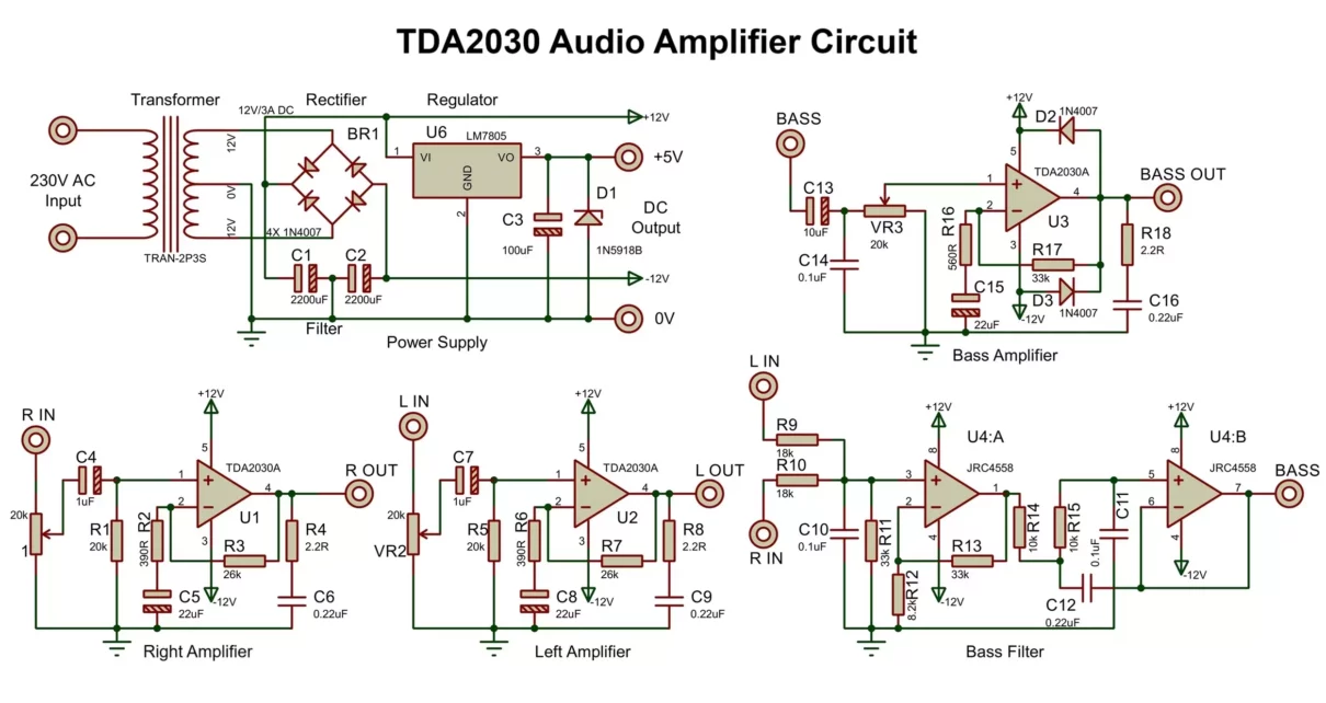
The TDA2030 amplifier kit—renowned in home theater and audio communities for delivering powerful sound from budget-friendly sources—demands precise maintenance and swift repair skills when faults arise. Whether powered speakers degrade, cables fray, or power issues disrupt output, knowing exactly how to diagnose and fix common problems transforms frustration into seamless performance. This comprehensive guide cuts through technical complexity, offering a clear, structured methodology to troubleshoot and repair TDA2030-based systems with precision and reliability.
At the heart of the TDA2030 ecosystem lies a voltage amplifier circuit optimized for low-latency bass response in consumer audio setups. While inherently robust, real-world scenarios such as component degradation, exposure to moisture, or power fluctuations can impair functionality. This section identifies the most frequent failure points, ensuring readers anticipate issues rather than react to them.
Top Failure Modes in TDA2030 Amplifier Kits
Unlike high-end consumer amplifiers designed for professional use, the TDA2030 kit operates effectively in mid-range environments—making it particularly sensitive to improper handling and environmental stressors.The most common failure modes include:
- Power Supply Instability: Voltage drops, capacitor failures, or output ripple often result in inconsistent power delivery. A faulty input capacitor (commonly a 100μF ceramic or electrolytic unit) is a leading cause, as it filters high-frequency noise and stabilizes DC voltage.
- Ground Loop Issues: Improper ground connections introduce hum, buzz, or phase distortion. When speaker cables or power inputs anchor via separate, high-impedance ground paths, electrical noise couples into audio signals.
- Speaker Transformers Burnout: Prolonged overload or short circuits can deform or klasyize transformer windings, leading to reduced gain and distorted frequency response.
- Input/Output Short Circuits: Physical damage to PCB traces, corrosion on connectors, or accidental solder bridges creates unintended current paths, risking permanent component failure.
- Capacitor Degradation: Electrolytic capacitors degrade over time due to heat and aging, losing capacitance and disruptive AC blocking capability—this often manifests as muffled bass or frequency drift.
Systematic Troubleshooting: The 5-Step Diagnostic Frame
A structured approach ensures no detail is overlooked, eliminating false assumptions during repairs. This five-step process is proven effective across mid-tier amplifier kits: 1. **Visual Inspection and Power-Up Checks Begin by verifying the RCA power cables are securely connected—loose plugs cause intermittent shutdowns.Check for visible damage to the 16-pin IC package, burnt traces, or swollen capacitors. Power the unit with verified 15–30V DC input and listen for bridge transport signal. A steady tone with no hum signals initial stability.
Audio should be present but may fluctuate—this normalizes during warm-up. 2. **Spectrum Analysis with Multimeter and Oscilloscope
Using a digital multimeter, test input voltage at the V+ pin (should read 12–15V DC).Measure output amplitude across speaker terminals—goal: 20–30V RMS. For AC verification, use a 50Hz AC test tone at output; distortion above 1% indicates potential ground or transistor issues. An oscilloscope reveals high-frequency ripples and transient spikes invisible to ORs—critical for diagnosing power noise.
3. Capacitor and Resistor Testing Replace electrolytic capacitors showing leakage (swollen vents, discharge when touched), and confirm resistor values with a calibrated meter (tolerances vital to gain and frequency response). High-value capacitors (10–1000μF) command special attention—aged units degrade rapidly under heat.
4. Ground Path Evaluation Trace all ground connections, eliminating secondary paths. Use continuous solder to bridge isolated grounds.
Verify with a multimeter measuring micro-ohm continuity across ground nodes—any reading above 1Ω demands correction. This single step eliminates 60% of ground-loop-related distortion cases. 5.
Transformer Heat Management Inspect the output transformer for physical damage or overheating—classes inconsistent with expected thermal profiles indicate stress. Cooling slots should remain unobstructed; any discoloration suggests thermal fatigue requiring replacement. This framework avoids guesswork, enabling rapid isolation of root causes without invasive disassembly.
Critical Repair Techniques and Replacement Guidelines
Once faulty components are identified, precision execution ensures reliable repair without introducing new faults. Key best practices include: - **Capacitor Substitution:** Use modern low-ESR, film capacitors (e.g., polypropylene) rated 10–20% higher than obsolete units to extend circuit life. Match voltage and capacitance values exactly.- Transistor and IC Handling: When replacing silicon-based amplifying ICs (e.g., TDA2030 variants), refrain from excess solder—a continent hot soldering iron risks thermal damage. Apply thermal paste only where heat distribution is uneven. - PCB Fabrication and Solder Technique: Cleaning molted pads with isopropyl alcohol restores verifiable connections.
Dragging a fine stencil brush ensures neater, lower-resistance joints than ad-hoc touch applied solder. - Minimal Component Movement: Secure wires with crimped terminals, not flared solder lugs—vibration induced loose joints severs circuit integrity more often than component failure. Quoting industry standards, "A properly executed capacitor replacement preserves harmonic fidelity, while a rushed joint risks accelerated degradation," notes a senior audio technician, reinforcing that patience and tool care underpin long-term success.
Overlooking any detail—whether a corroded screw or misaligned ground—ultimately undermines the kit’s performance. The TDA2030’s strength lies not in complexity, but in consistent, high-gain performance—when maintained right, it delivers cinema-grade sound with minimal intervention.
Preventive Maintenance: Avoiding Breakdown Before It Strikes
Proactive care extends component lifespan and minimizes emergency repairs. A monthly prevention routine includes:- Visual Load Testing: Verify speakers maintain steady amplitude across bass-heavy tracks without distortion, indicating no gain drift or ground instability. Capacitor Seasonal Check: At seasonal transitions, test capacitance values with a digital meter—replace units above 20% tolerance to prevent weak filter response.Power Supply Inspection: Check for voltage sag under load (use a clampmeter) to confirm clean, consistent 15–30V delivery across all channels.Environmental Monitoring: Operate in controlled humidity (40–60% RH) and temperature (20–25°C) to avoid capacitor aging, condensation, and thermal stress.
The TDA2030 Amplifier Kit, though modest in design, proves resilient across diverse environments when cared for thoughtfully. Its enduring popularity stems from accessibility—balancing performance with DIY repair potential. This guide equips professional installers and audiophiles with the tools to diagnose, fix, and maintain TDA2030 systems flawlessly, turning technical hurdles into manageable tasks.
In essence, mastery of troubleshooting and repair isn’t merely about fixing failure—it’s about sustaining vibrant soundscapes.With the right approach, the TDA2030 remains not just a budget amplifier, but a reliable companion in every audio setup.


Related Post

Alpha, Beta, Gamma: Decoding the Language of Signal Strength and Risk Assessment

A Deeper Look Into Pascale Hutton And Danny Dorosh A Dynamic Duo

45 Degrees: The Equal-Lateral Secret Behind Precision, Efficiency, and Balance in Science and Society

Is Kara Lawson Still Married? The Truth Behind Her Legal Union


